Journal of Multimedia Theory and Applications (JMTA)
ISSN: 2368-5956

Volume 1, Year 2014 - Pages 60-69
DOI: 10.11159/jmta.2014.007
Echolocating with Ultrasound: A Usability Analysis
Alan Deacon1, T. Claire Davies1, Shane Pinder2
1University of Auckland, Mechanical Engineering, Private Bag 92019, Auckland, 1142, New Zealand
c.davies@auckland.ac.nz; ajdeaco@hotmail.com
2Manukau Institute of Technology, Manukau Engineering, Auckland, New Zealand
sdpinder@gmail.com
Abstract - Individuals who are totally blind do not have access to visual stimuli, thus one must account for other relationships with nature that provide information to enable effective locomotion and travel. Typically a primary mobility aid such as a long, white cane or a guide dog are used, but these are unable to detect obstacles that are not ground based including tree branches, windows that open outward and wall mounted bookcases. A device known as the AUDEO (audification of ultrasound for the detection of environmental echoes) has been developed as a means to providing information about obstacles above waist height to people with visual impairment. This is expected to be used in addition to a primary mobility aid, but intended to give the individual more confidence in travelling in unknown environments where head high obstacles may exist.
Keywords: Audification, Mobility devices, Visual impairment, Obstacle avoidance, Vertical localisation.
© Copyright 2014 Authors - This is an Open Access article published under the Creative Commons Attribution License terms. Unrestricted use, distribution, and reproduction in any medium are permitted, provided the original work is properly cited.
Date Received: 2013-09-17
Date Accepted: 2014-02-05
Date Published: 2014-02-24
1. Introduction
Motivated by the large number of visually impaired and blind people worldwide, and the related prevalence of injuries caused by head-level obstacles, there is a need for advancement in the design of navigation and secondary assistive devices. Furthermore, due to the aging trend within the world s population [1] and the correlation between age and vision impairment, these issues are likely to increase in the coming years.
A survey of 300 legally blind or functionally blind individuals from the United States of America was conducted by Manduchi and Kurniawan in 2011 and investigated the frequency, nature, and causes of head-level and fall accidents [2]. Of the 300 respondents, over half acknowledged that they had at least one head-level accident a year, with over 12% experiencing mishaps more often than once a month. The respondents were also questioned about the environments in which these accidents occurred. Eighty-six percent reported outdoor collisions mainly with tree branches, but others included contact with signs and poles. The indoor accidents tended to occur as a result of bumping into shelves, tables, and staircases, or doors and cabinets being left ajar.
The accidents are often serious with 23% resulting in some medical consequence, 60% of those requiring professional medical assistance for stitches, staples, or dental treatment for broken teeth. The accidents had lingering effects on many people with 43% suggesting that they had changed their walking habits due to an accident, usually walking slower or protecting their head with a raised arm as they walk, and 26% feeling less confident in independent travel. Some respondents commented that they avoid certain areas or require sighted companions to accompany them.
Falls are another significant area of risk. Only 8% of the respondents in the same study said that they had never experienced a trip resulting in a falling incident [2]. Over 35% said that they had such occurrences happen more than once a year. Those who were blind (with at most light perception) as opposed to legally blind (who meet the criteria to be legally blind, but can perceive shapes) were twice as likely to be involved in a tripping or head-level injury. A correlation also existed between those walking into objects and those having falls.
Manduchi and Kuriawan's study also showed how uncomfortable many of the individuals were in unfamiliar environments [2]. Of the individuals surveyed 40% would only travel unfamiliar routes once per week (if any) and 22% would not leave their residence more than 5 times a week. It was discovered that the respondents that used guide dogs tended to travel more that those using long canes. This suggests that a good aid defines the comfort zone and the likelihood of adventure.
2. Related Work
John Neuhoff described the detection and recognition of sound as "the result of a complex interaction of physics, physiology, sensation, perception and cognition" [3]. The focus of this research was to maintain the majority of these interactions naturally while incorporating the physical design of an assistive technology to be used by individuals with visual impairment as a secondary mobility device.
Several sonar devices have been developed to help increase the preview distance before physically contacting obstacles, but few have gained acceptance. These devices are used in addition to a long white cane and are termed secondary mobility devices [4-6]. Sonar devices include the Trisensor and Sonic Pathfinder and convert echo information into audible information.
A significant advantage of sonar relative to that of echolocation is that it may not be as sensitive to the factors that affect audible echolocation. For instance, the quality of the signal can be improved by increasing the transmitter power. Since other individuals cannot hear the signal, an increase in the power does not affect others. In an auditory situation, absorption results in a lower sound pressure level, making it too soft to hear. If the transmit power is increased at ultrasound, absorption still occurs and decreases the signal strength, but ultrasound receivers are also more sensitive than the ears at picking up high frequency reflections. As a result, characteristic textures can more easily be detected with ultrasound than within audition. Ambient noise that influences interpretation of sounds in the auditory range does not affect the reflected signals in the ultrasound domain. Sounds that may not be heard in the auditory range will still generate a reflected ultrasound signal.
The basic premise of the current sonar secondary mobility devices is that ultrasound information is transmitted by a wide-angle beam ultrasound transducer and received by other transducers. Information from the backscatter of ultrasonic waves is transmitted to the ears.
There are two devices that are fairly common when referring to sonar secondary aids. These are the KASPA developed by Dr. Leslie Kay [4, 5] and the Sonic Pathfinder developed by Dr. Anthony Heyes [6]. Additional focus on these systems is further presented.
The Trisensor, later termed the Sonic Guide and more recently the KASPA, was developed by Kay in 1962 as a "wide-angle binaural" ultrasonic aid [4]. A transmitter and two receivers are mounted on the nosepiece of a pair of glasses. Information from the backscatter of ultrasonic waves is transmitted to the ears binaurally using sonification of the signal such that interaural intensity differences represent directional differences, and pitch indicates the distance to an obstacle. This device is a continuous scanning device that provides tones about all obstacles in the environment regardless of motion of the user or look direction. As the sonified signal is not developed to minimise masking, other aspects of the surroundings cannot easily be heard. An individual using this device cannot readily communicate with those around, limiting the device solely to independent travel situations.
The Trisensor only portrays information using interaural intensity differences [7]. This system does not consider the effects of head related transfer functions and interaural time differences, nor does it portray sufficient information about the spatial environment to be able to effectively identify slopes and curvature, even by an individual with considerable practice.
The Sonic Pathfinder developed by Heyes in 1984 is currently one of the least expensive available secondary detection systems. This device is a pulse echo digital device that uses a musical scale to represent obstacles in the path of the user [6]. This device uses two transmitter transducers and three receivers to cover the field of view. It prioritises the obstacle immediately in front of the user and does not provide any additional information until the obstacle is beyond the field of view. The Sonic Pathfinder uses earcons in the sense that as a person approaches an obstacle, the tone increases or decreases along an Ionic scale (the most common musical scale). Although this is acceptable for the obstacle nearest the individual, it does not represent the spatial environment as a whole. As the distance from the obstacle in the "frame of reference" decreases, the pitch of the tone decreases.
3. Identification of System Requirements
The AUDEO attempts to address the issues experienced with the aforementioned devices. Usability testing with the AUDEO has been conducted with blindfolded, sighted participants under anechoic conditions and has focused on sound localisation [8], distance approximation, and aperture passage [9]. The first two tests were designed to evaluate a participant s ability to accurately interpret the auditory information in a way that could be used to locate the position, both direction and distance, of an environmental obstacle relative to a user. The aperture passage experiment demonstrated how the method of echolocation could be used in everyday situations.
There were however, several usability issues identified during this testing. First, the device was larger and more bulky than would be intended in a final design. It was hypothesised that different, or more accurate results, might be obtained if the individuals were not constrained by the size of the prototype [8,9]. Secondly, the orientations of receivers were limited to two directions. These two orientations were supposed to be representative of the same direction as the eyes and the same direction as the ears. Although both appeared effective in the judgement of distance and the ability to avoid apertures, it became apparent during the testing of localisation that in fact the ears have a complex structure that neither faces outward nor forward. Looking toward a sound not only allows an individual to use vision to more precisely locate it, but also brings that sound into the area which can most easily be interpreted, that which allows similar information in both ears, or the area immediately in front of the individual. The second hypothesis was that a device that can capitalise on the shape of the ear may result in better localisation ability and be more usable.
The purpose of this paper is to detail the further development process of the AUDEO device to make it both smaller and better able to capitalise on the shape of the ear, thus increasing vertical localisation and usability. Hearing aids have been manufactured in various guises since the 1800 s; initially bulky ear horns, the hearing aid of today can be entirely contained within the ear canal of a user [10]. There is a tremendous amount of research and trial and error development on which to draw. The earpiece design for the AUDEO technology incorporated solutions from earlier hearing aid designs that have overcome issues of diminished localisation and occlusion.
4. Background and Theory
For individuals with visual impairment, localisation is often achieved by interpreting sounds within the environment. The AUDEO device capitalizes on echolocation, Doppler shifts and down conversion of the ultrasound signals to provide useful auditory information to the user.
4.1. Echolocation
Echolocation uses the sound localisation principle. Sound reflects off environmental obstacles allowing for directional detection. There are two forms of echolocation. The first, known as active echolocation, results when an individual provides a sound to the environment that reflects. Another form of echolocation is passive echolocation in which the individual uses environmental sounds to detect obstacles within an environment. For example, some shops have music playing. This music will reflect and create a soundscape interpretable to the individual with visual impairment.
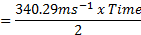
If an observer makes a sound, the reflected signals will return to that observer in the form of echoes. Distance can be determined between an observer and the reflector by the difference in time between the initiation of the sound and the return of its reflection (see Figure 1).
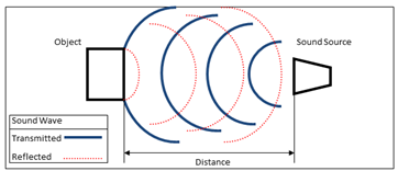
A sound wave travelling through air will move at approximately 340.29ms-1 *. Therefore the distance between an object and a sound source can be calculated as:
 |
 |
 |
The direction of the reflection, as determined by sound localisation, defines the directional origin of the object.
4.2. Doppler Effect
The Doppler Effect describes a change in the frequency of a signal as a result of the relative motion between the transmitter (or a reflector) and the observer. A sound source moving toward an observer results in the waves immediately in front compressing relative to the emitted waves while those behind expand. This can be related as follows:

with c being the velocity of waves in the medium (air), vr representing the velocity of the receiver relative to the medium while vs represents the velocity of the source relative to the medium.
Although the AUDEO capitalizes on echolocation in the sense that the transmitted signal reflects off environmental obstacles, it differs from active echolocation as it provides a continuous ultrasonic signal rather than a discrete chirp. The relative difference between an observed and emitted frequency at ultrasound is much larger than in the auditory range, allowing the AUDEO device to better present environmental reflections than a typical auditory echolocation process.
4.3. Doppler Shift
The AUDEO device transforms the received high frequency sound reflections to an audible range via the process of direct down-conversion [11]. Using a 40 kHz sampling rate equal to that of the transmitted signal, the sound is intentionally aliased so the final output is the difference between the transmitted signal and the received signal. The difference between the two signals is caused by a Doppler shift that is created by the relative speed of the receiver and the object from which the echoes are reflecting.
At 40 kHz the signals that are transmitted and received are well beyond the normal human hearing range (as well as beyond the detection of dogs) which allows the device to be used in environments in which clicking or clapping of the hands is deemed socially unacceptable.
4.4. Down Conversion
The Doppler shifted, received signal described above is then down sampled by the intentional aliasing of the signal. Aliasing occurs when the sampling frequency is less than twice that of the frequency being sampled (Nyquist Criterion [12]). For many applications, such as the recording and playback of music, aliasing is avoided. Digital audio has a sample rate of 44.1 kHz or greater to allow frequencies below 22 kHz (those within the human hearing range) to be produced unaltered [13].
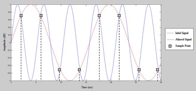
However, in the case of the AUDEO, the signal is intentionally aliased as follows. The resultant wave produced from an aliased sine signal will be equal to the difference between the initial signal and the sampling rate. This has been demonstrated in the example below (figure 7). A 200Hz sine signal (blue) is sampled at a rate of ~267Hz, as marked by the crosses. The resultant wave form (red) is the difference between the signal rate and sample rate (267 Hz � 200 Hz=) ~67Hz.
The AUDEO device receives the Doppler shifted signal and samples it at the 40 kHz transmission frequency. The resultant waveform is equal to the difference in frequency from the transmitted and received signals. This produces a signal within the audible range that is amplified and then provided to the user via speakers.
5. AUDEO System Design
A miniaturised AUDEO PCB was created to research the possibility of reducing the size of the transmitter circuitry. The PCB propagated an ultrasound wave that was created by an ATMega168 microcontroller (Atmel ATMega168) timed with a crystal oscillator. The microcontroller created a 4 Vpk-pk square wave at a frequency of 40 kHz. This wave was propagated with a ST100 ultrasound transmitter. The audible range of the AUDEO device under these conditions was limited to approximately 1.0 m. Additional strategies to increase the range were then explored.
5.1. Wave Manipulation
The purpose of wave manipulation was to increase the possible range of the transmitted sound signal. First, the square wave was converted to a sine wave as it is a more efficient means of power transmission. Second the sine wave was amplified to increase the power and therefore the transmission range of the signal.
In the first stage of the conversion, the square wave from the microcontroller is passed to a difference amplifier with a gain of two. The square wave signal is compared to a constant 2V signal produced by a voltage divider from the power source. The use of a difference amplifier was used to centre the output voltage about 0 V, this way the peak-peak voltage was made larger before clipping occurred.
The amplifier was chosen due to its low slew rate. By setting the gain of the amplifier to 2x when the square wave switched between its high and low state, the output wave did not have enough time to reach the peak voltage because of the high frequency. The resultant output was instead a triangle wave with a frequency of 40 kHz and amplitude of 6 Vpk-pk.
The 6-Vpk-pk wave was then passed to a low-pass passive filter. Low-pass filters are created using a resistor in series to a signal and capacitor in parallel. A low-pass filter allows for frequencies below the set value to pass while high frequencies are removed. This frequency value is proportional to the capacitor and resistor.

As a triangle wave is combination of multiple harmonic frequencies starting from its fundamental frequency, by removing the frequencies above 40 kHz the resultant wave form was a pure 40 kHz sine wave.
Finally the sine wave produced by the low-pass filter is passed to a second amplifier. The second amplifier has a significantly higher slew rate and does not alter the shape of the waveform but simply amplifies it.
5.2. Sample and Hold
The down-sampling of the received ultrasound signal allows conversion of the ultrasound into a signal range at the audible level. This was achieved using a sample-and-hold integrated circuit (IC). A sample-and-hold IC operates by sampling a signal at an input rate defined by a clock input. Once the clock is triggered the IC takes the value of the signal at the time then this value is held until the negative clock edge at which time the voltage drops to ground
5.3. Information Processing
The last stage is information processing. Following the sample-and-hold is a resistor-capacitor (RC) low-pass filter. The purpose of this filtering stage is to remove noise from the signal before passing it to the speaker. In this case, a resistor of 4Ω is used in combination with a capacitor of 22µF. This can be explained through the calculations below that relate to the velocity of the user s movement.


The frequency of 1800 Hz, for instance, represents a relative velocity of


As the sound wave travels from the observer then back again the relative velocity is half of this value.

Under the controlled environment in which an individual typically walks, this velocity is not likely to be exceeded. Therefore any noise above this frequency can be removed.
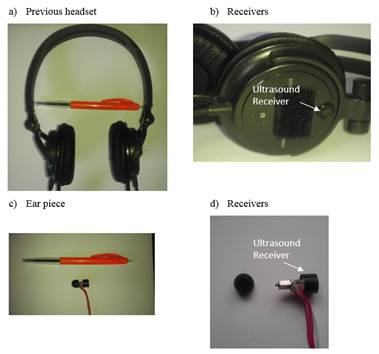
6. Receiver Design
Previous designs had the receivers placed externally on a headset (Figure 3 a and b: Sony Dynamic Stereo Headphones MDR-V250). One of the issues identified by the earlier testing of the device was that the shape of the ear and its reflections contribute heavily to the ability of a person to localise sound vertically. It was decided that an in-the-ear design was required.
6.1. Down-conversion Circuitry
The down-conversion circuitry had originally been placed within the earpiece of the headset. For down-conversion to occur, an operational amplifier (OpAmp) was required to amplify the received signal and a sample-and-hold IC to sample the signal down to audible frequency. These components also required a printed circuit board (PCB) on which to mount the components. To power the down-conversion circuitry the OpAmp requires +9-V and -9-V power supplies for its positive and negative rail respectively and a ground signal to create an inverting amplifier. The sample-and-hold IC also requires the 9-V power supply, a ground reference, and a 40-kHz clock signal to be used as a sample rate. To transfer the power and signal lines five separate wires are required between the ear piece and the main transmitter circuit board (mounted in the headset).
The design was enhanced by moving the down-conversion and amplification circuitry to the main transmitter PCB. This reduced the number of lines to connect the earpiece with the transmitter to three. The modified version required only a ground line, an output line from the ultrasound receiver to the amplification circuitry, and an input line for the 'in ear speaker from the down-conversion circuitry. Rather than having individual OpAmps for each of the ear pieces these can be combined in a single dual- or quad-OpAmp IC, thereby reducing the number of parts. Furthermore, space was saved in the ear piece by not requiring the PCB or electronic components.
6.2. Earpiece Design
Typically, hearing aids are either custom designed for the user s specific ear shape and size or the user is fitted based on a range of pre-designed moulds [4]. The principal goal for individual fitting of hearing aids is to ensure comfort and to enhance communication skills [15]. However for the usability testing of the AUDEO device it was deemed that the time taken to individually fit each participant was not practical. The ear piece was instead designed to be flexible in its use so that a range of participants would be able to comfortably and efficiently use the device.
There were three key requirements for design of an ear piece. The ear piece was to:
- hold firmly in place a speaker and ultrasound receiver;
- be flexible and fit any number of users, and;
- be able to be cleaned and reused.
After an iterative design process, the solution was to use headphone ear buds. Phillips ErgoFit headphones provide a range of rubber ear bud sizes. The rubber ear buds fit firmly around the speaker (Knowles Acoustics) and allow the unit to fit firmly and comfortably within the ear. Additionally, the Ergofit range allows the ear buds to be fitted to the individual user and also can be removed and cleaned between test participants (Figure 3 c and d).
6.3. Maintaining Audible Range Sound
The AUDEO hearing piece fits tightly in the ear of the user. Sound can only enter the ear through the speakers. The speakers are fed by the sound taken in from the ultrasound receiver. The bandwidth of the ultrasound receiver is narrow and will only receive sound close to the 40 kHz frequency; this means that the normal audible range (i.e. sound frequencies of 20-20kHz) is not picked up. To resolve this issue a secondary receiver could be used to provide the lower audible range information. Simply by using a lower frequency receiver and summing this input with the down sampled AUDEO feedback, it should allow audible communicated information to be retained.
Alternatively, vents could be used to allow this sound to travel into the ear. Vents have been used in ITC hearing aids to reduce the occlusion effect [16]; however they could in this instance create a path through which audible information could travel into the ear canal.
7. UsabilityTesting- VerticalLocalisation
The miniaturized device was designed to increase usability as well as to increase localisation ability. The aforementioned tests [8, 9] had identified that vertical localisation was an issue with the previous version of the device. It was now important to test the ability of human participants to localize using this new version of the device. The purpose of the usability testing was to compare the ITE version of the device, with the previous version of the device (out of the ear or OTE).
7.1. Participants
A group of 10 adults ages between 20-30 years volunteered for this study. All participants were in good health, without visual impairment and with no physical disabilities that would affect their capacity to complete this study. None of the participants had previous experience with the AUDEO device prior to the testing period. Participants gave written, informed consent to this study in accordance with the guidelines of the University of Auckland Human Ethics Committee. The participants were blindfolded during testing to simulate vision loss. There is evidence that blindfolded participants can quickly learn to compensate for loss of sight [17].
7.2. Experimental Protocol
This experiment followed a similar process that Davies et al. used to assess a person s ability to localise sound in earlier experiments [8]. A participant was seated in front of an array of speakers placed vertically. A white noise was produced and the participants were asked to identify the source speaker.
7.3. Test Procedure
The participants were first tested with the ITE placement of the receivers. To demonstrate how the system worked, sounds from each of the five transmitters were played once, in sequence from top to bottom, and they were clearly identified by the tester. The participant was then blindfolded. A random transmitter produced an encrypted white noise signal for the duration of two seconds. The participant attempted to identify the source of the transmission. The participant was then told which transmitter had actually been used.
Feedback was given to the participant to simulate the learning process that an end user may undertake when learning device use. A group of 25 signals were produced and played semi-randomly through the transmitters so that each of the transmitters was used five times.
7.4. Variables Assessed
7.4.1. AUDEO Receiver Placement
We hypothesised that the placement of the receivers in the ear would allow for better localisation than the out of the ear version as vertical sound localisation should be aided by the ear pinna when the receivers were placed inside the ear.
7.4.2. Transmitter Position
An experimental rig was created for testing that placed five ultrasound transmitters in a one meter arc at angles of 15o with each of the transmitters facing inwards towards the centroid of the arc where the participant was seated. The transmitters were numbered 1 to 5.
7.4.3. Correct Predictions, F(c)
The participant s ability to detect a sound source in the vertical plane was compared with percentage values. First was the percentage of correct guesses. This considered the occurrences when the participant selected the correct source of the signal.
7.4.4. Above or Below Predictions, F(ab)
A measure was taken to determine whether a participant was able to differentiate between sound sources above or below them. This value was calculated by identification of transmitters 1, 2 (above) or 4, 5 (below). For example, if transmitter 2 was used to produce a signal, a prediction of 1 or 2 would be considered correct as both values are above centre, whereas values 3, 4 or 5 would be considered incorrect. Similarly if transmitter 5 was used, a prediction of 4, 5 would be correct, whereas 1, 2 and again 3 would be considered incorrect.
7.5. Statistical Analysis
Analyses of Variance (ANOVA) were used to identify the underlying population differences under the various conditions. TUKEY post-hoc analysis was performed to report any specific differences.
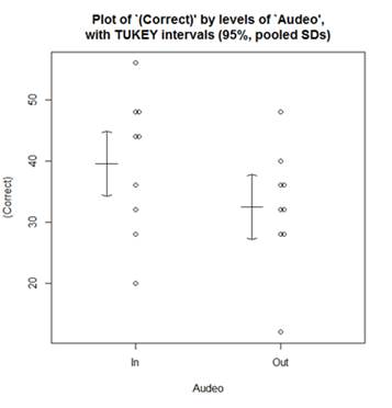
An analysis of variance showed that there was no evidence that the placement of the receiver influences the participant s ability to correctly identify the actual location of the sound source F(c) =1.414 (p > 0.12) (Fig. 4). Of the ten participants, eight scored higher while operating the ITE compared to the OTE, one received identical results, only one of the ten participants performance decreased using the ITE design. This participant population scored on average ~7.2% higher for the ITE design than the OTE during testing.
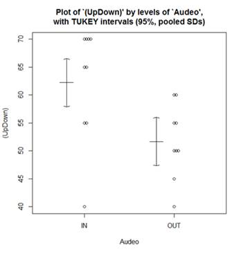
When judging whether a sound has come from above or below the participant, there is evidence to suggest that the percentage of correct predictions is higher for participants when they are using the ITE placement of the receivers when compared to the OTE F(ab)=2.5796, (p<0.05) (Fig 5). Observations showed that, of the ten participants, nine scored higher while operating the ITE. We are 95% confident that the ITE design will result in an increase of up to 19.2%.
8. Discussion
From research into vertical sound localisation, it was believed that the ear pinna had a significant influence on a person s ability to differentiate sounds in a vertical plane. It was hypothesised that the ITE earpiece would retain more of the spectral cues provided from the pinna than the original OTE earpiece and in turn would result in improved performance during the vertical sound source localisation experiment.
The evidence from the vertical localisation testing, however, was not significant enough to suggest a difference in population averages between the ITE and OTE earpieces under the correct prediction condition. Despite this, the ITE design demonstrated better results for 80% of the participants from the limited population. Overall from the 10 participants, the ITE design performed better than the OTE design by a range of 37.2% to 30%. There was evidence, however, that the broader vertical understanding from the AUDEO device is improved with the ITE design. Both of these two conditions are, however, significantly better than what would be expected from a random selection of the five transmitters. This is attributed to the directionality of the ultrasound receivers, each receiver would decrease in sensitivity by 6dB per 30o diversion from the centre, and this would mean that there may be slight difference in amplitude between the higher and lower transmitters and those positioned in the middle.
When instructing the participants on how to undertake the vertical localisation section of the test, they were asked to name which of the five transmitters had produced the white noise signal. They were not instructed as to whether or not they were allowed to move their head vertically. Interestingly, of the 10 participants tested, only one attempted to move the head in an attempt to gain more information. This participant moved his head in a scanning pattern from top to bottom. However, this did not appear to benefit the individual who managed only 32% correct for both the ITE and OTE designs.
9. Conclusion
The earpieces were designed to test the hypothesis that the placement of the receivers would improve a user s ability to localise vertical sounds by retaining the natural spectral cues generated by the ear pinna. Miniaturising the earpiece, from the large over ear earphones to smaller ear buds, allowed the receivers to be positioned much deeper inside the ear. As a result of the redesign there was a noticeable improvement in the vertical localisation ability of the participants using the ITE when compared to the results of the previous OTE style. The evidence suggests an improvement for the broad understanding of what is above or below them. Further testing with the new version of the device is warranted to evaluate whether better localisation may be achieved.
References
[1] Haub, C. World Population Aging: Clocks Illustrate Growth in Population Under Age 5 and Over Age 65. 2011 [cited 2013 28 January]; Available from: View Article
[2] Manduchi, R. and S. Kurniawan, Mobility-Related Accidents Experienced by People with Visual Impairment. Association for Education and Rehabilititoin Journal, 2011. 4(2): p. 11. View Article
[3] Neuhoff, J.G., Ecological Psychoacoustics. 2004, New York: Academic Press. View Book
[4] Kay, L., Auditory perception of objects by blind persons, using a bioacoustic high resolution air sonar. Journal of the Acoustical Society of America, 2000. 107(6): p. 3266-3275. View Article
[5] Kay, L., Bioacoustic spatial perception by humans: a controlled laboratory measurement of spatial resolution without distal cues. J Acoust Soc Am, 2001. 109(2): p. 803-8. View Article
[6] Heyes, A.D., The Sonic Pathfinder - a New Electronic Travel Aid. Journal of Visual Impairment & Blindness, 1984. 78(5): p. 200-202. View Article
[7] Easton, R.D., Inherent problems of attempts to apply sonar and vibrotactile sensory aid technology to the perceptual needs of the blind. Optom Vis Sci, 1992. 69(1): p. 3-14. View Article
[8] Davies, T.C., Pinder, S. D., Dodd, G., Burns, C. M., Where did that sound come from? Comparing the ability to localise using audification and audition. Disabil Rehabil Assist Technol, 2012. 7(2): p. 130-8. View Article
[9] Davies, T.C., S.D. Pinder, and C.M. Burns, What's that sound? Distance determination and aperture passage from ultrasound echoes. Disabil Rehabil Assist Technol, 2011. 6(6): p. 500-10. View Article
[10] Vohringer, C.G., CIC Hearing Aid. 2006: United States. View Article
[11] Davies, T.C. and S. Pinder, Exploring Direct Downconversion of Ultrasound for Human Echolocation. 2007. View Article
[12] Shannon, C.E., Communication in the presence of noise. Institute of Radio Engineers, 1949. 37(1): p. 10-21. View Article
[13] Self, D., Audio Engineering Explained, ed. T.F. US. 2012. View Book
[14] New Zealand Audiological Society Inc, Hearing Aid Selection Fitting and Follow-Up. 2008. View Article
[15] Sickel, K., Baloch, S., Bubnik, V., Melkisetoglu, R., Azernikov, S., Fang, T., Hornegger, J., Semi-Automatic Manufacturing of Customized Hearing Aids Using a Feature Driven Rule-based Framework. Proceedings of the Vision, Modeling, and Visualization Workshop 2009 (Braunschweig, Germany November 16-18, 2009), 2009: p. 305-312. View Article
[16] Ross, M. The "Occulsion Effect" - What it is and What to Do About it. 2004 9 September 2011 [cited 2013 29 Jan]; Available from: View Article
[17] Loomis, J.M., Klatzky, R. L., Golledge, R. G., Cicinelli, J. G., Pellegrino, J. W., Fry, P. A., Nonvisual Navigation by Blind and Sighted - Assessment of Path Integration Ability. Journal of Experimental Psychology-General, 1993. 122(1): p. 73-91. View Article
* The speed of sound is variable relative to humidity and temperature
** The time is divided by 2 as the total distance the sound wave travels from the source, to the object then back to the source (Figure 1).